Civil 3D 2020 to 2022 Alignment Essentials
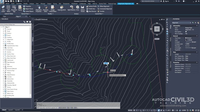
You create alignments as a combination of lines, curves, and spirals that are viewed as one object.
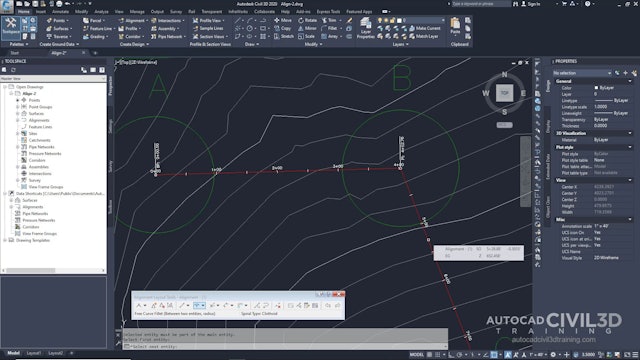
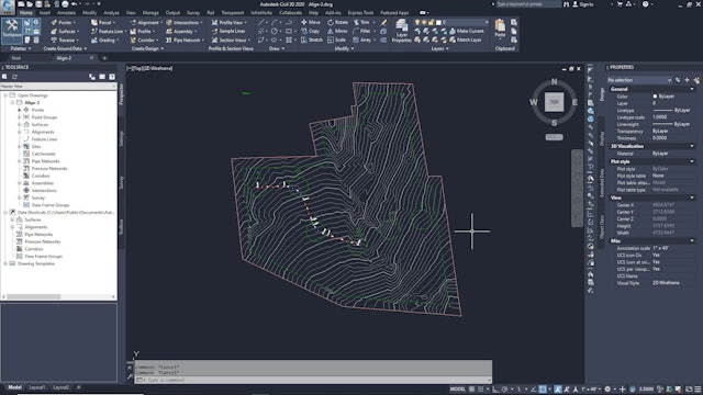
Alignment objects can represent road centerlines, pipe networks, and other construction baselines. Creating and defining a horizontal alignment is one of the first steps in roadway, railroad, or site design. You can draw the alignment geometry as a polyline, and then create the named alignment from that geometry. For greater control, you can create an alignment object using the Alignment Layout Tools. You can also make edits to alignments using grips, or the commands on the Alignment Layout Tools toolbar, while automatically maintaining tangency between the alignment components.
Alignments can be stand-alone objects or the parent object of profiles, sections, and corridors. If you edit an alignment, the changes are automatically reflected in any related objects.
When creating an alignment, assign it a type of centerline, offset, curb return, rail, or miscellaneous. You can use these alignment types to categorize your data based on alignment function. Select the centerline type for a road centerline, the rail type for a railway, or the miscellaneous type for other uses, such as a utility conduit. These types are independent objects.
-
01 Introduction to Creating Alignments
-
02 Creating an Alignment with the Alignment Layout Tools
-
03 Adding Free Curves and Spirals to an Alignment
-
04 Adding Floating Curves to an Alignment
-
05 Editing the Layout Parameter Values of an Alignment
-
06 Grip Editing an Alignment
-
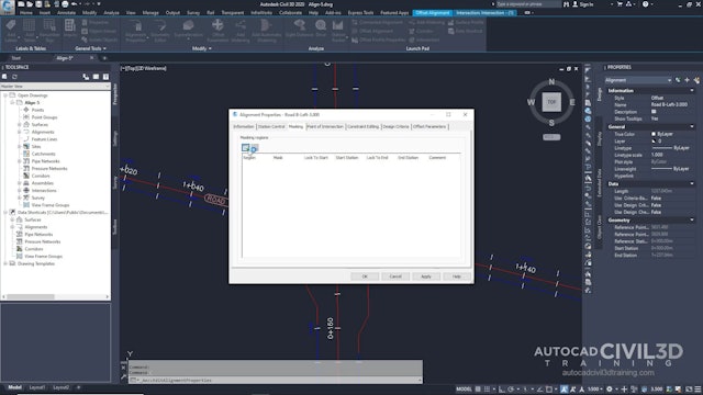
07 Applying a Mask to an Alignment

